Principle of operation
Functional diagram of the device is shown in Figure.
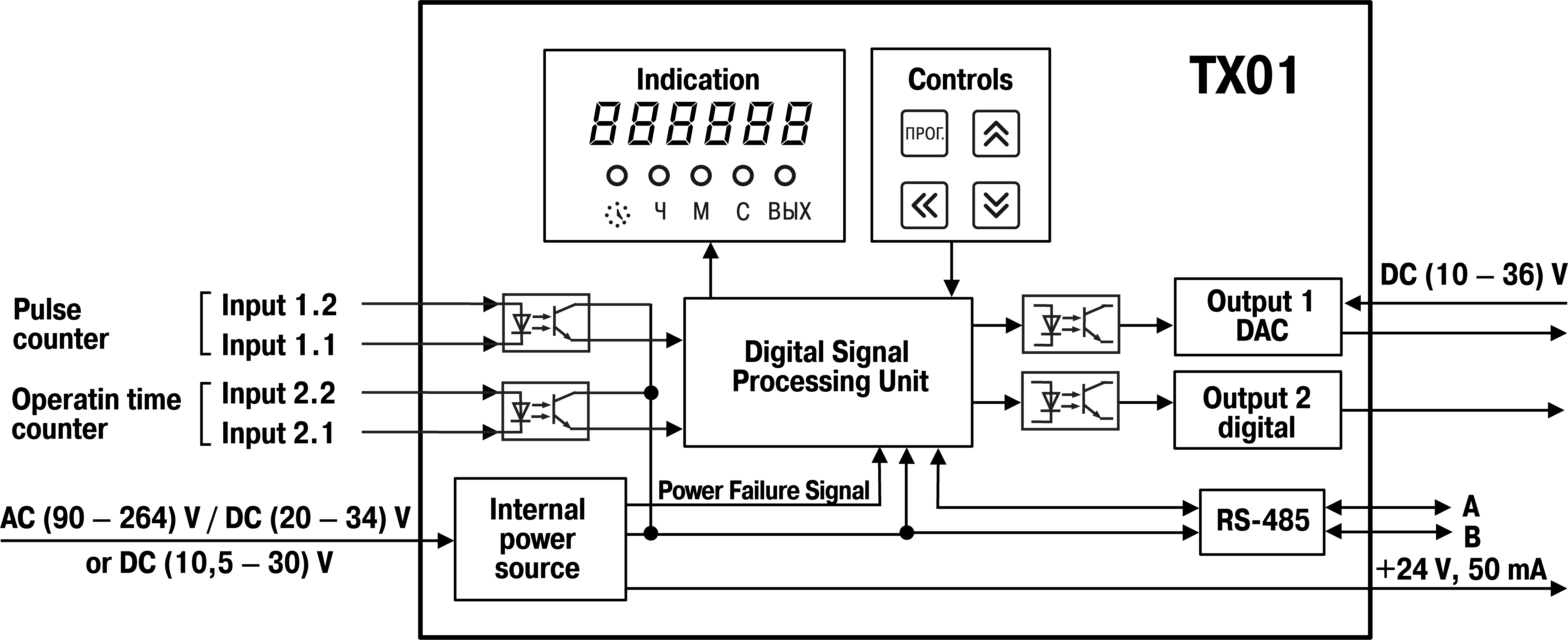
The device has two digital inputs for connecting sensors (pulse counter and operating time counter). To the inputs of the device can be connected:
- sensors with output n-p-n-transistor with an open collector;
- sensors with a dry contact type output (reed switches).
The counting input of the device receives pulses from a sensor that controls one or more marks on the motor shaft.
The levels of the input signals are converted and processed in the matching unit, after which they are sent to the digital processing unit, where it occurs:
- filtering of input signals;
- measuring the instantaneous value of the shaft speed;
- measurement of operating time at the operating time counter;
- conversion of measured values into real physical quantities;
- scaling of values before their output to the display;
- generation of signals for controlling the outputs according to a specified algorithm.
Control unit includes buttons for entering parameters and controlling the operation of the device.
Display unit displays the measurement results or operating parameters on the indicators and shows the device status using LEDs.
Internal power supply, depending on the version of the device (with AC or DC power), converts the supply voltage for all units of the device and generates a signal indicating the loss of supply voltage. It also generates a DC voltage to power the sensors connected to the inputs of the device.
Using the RS-485 interface, the device is connected to a PC, which makes it possible to set and edit the configuration of the device, to monitor its current status and readings.
Control and indication
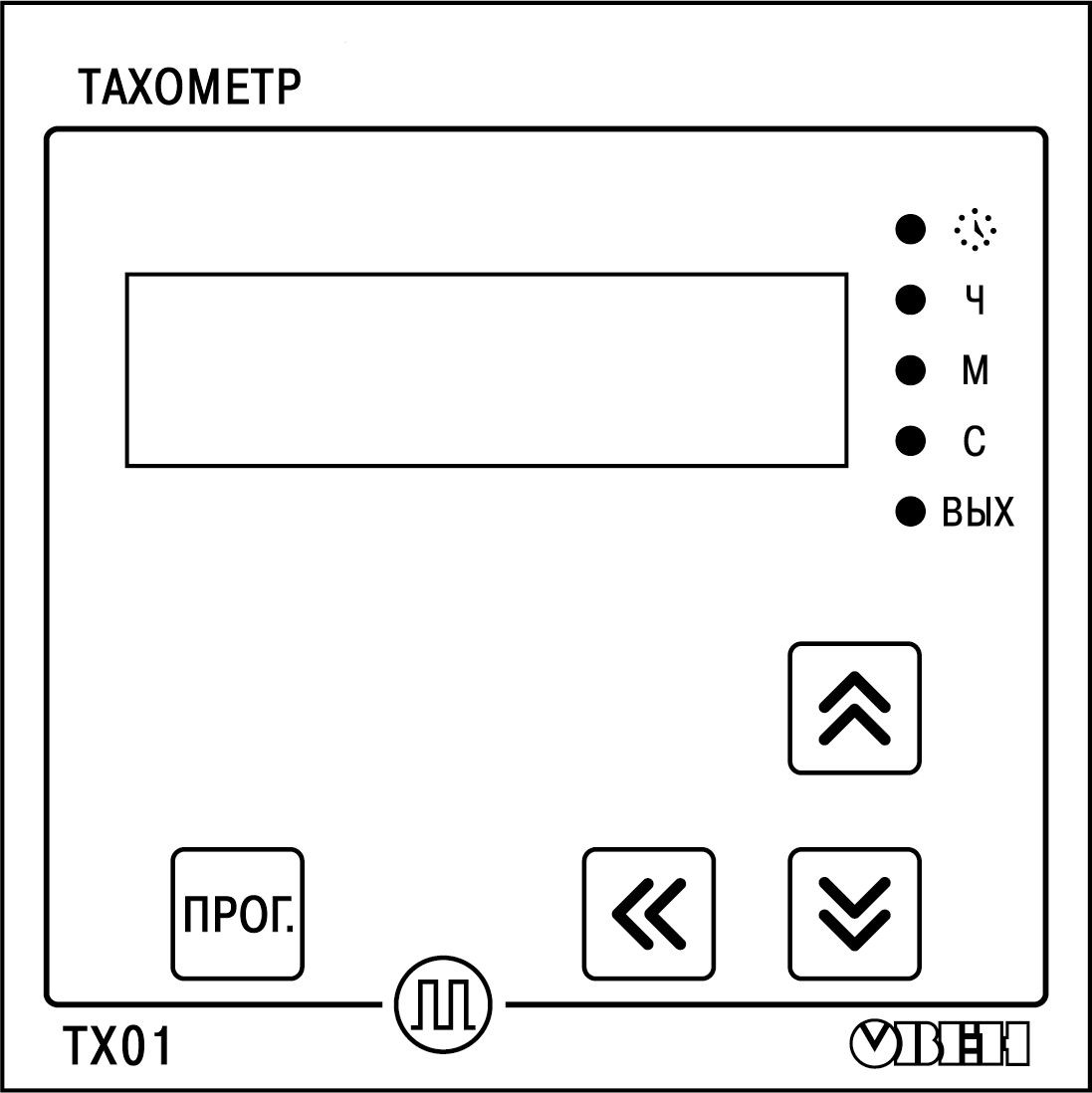
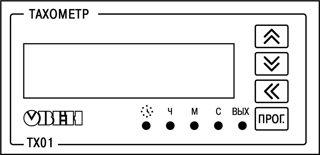
Elements of indication and control are located on the front panel of the device (see Figures and):
- seven-segment six-digit display;
- five LEDs;
- four buttons.
Display function
| Operating mode | Displayed information | Refresh rate |
|---|---|---|
| Tachometer | The current value of the pulse repetition rate obtained after filtering and averaging, taking into account scaling at the measuring input of the device | ≤ 6 s (equal to the duration of the time interval between the leading edges of the pulses at the measuring input of the device) |
If the pulse repetition rate is less than 2.5 Hz or the pulse source disappears, then the last measured value is displayed on the digital clock for 6 seconds, after which 0 will be highlighted. If the pulse repetition rate exceeds the maximum value with a positive tolerance of 2 % (FrEQ × 1.02), then the last measured value is displayed on the display for 6 seconds, after which the value recorded in the FrEQ parameter flashes. | ||
| Operating time counter | Operating time | 1 s |
| Setup | Parameter name and value | — |
Assigning LEDs
| LED | State | Value | |
|---|---|---|---|
| Tachometer mode | Operating time counter | ||
 | ON | Measurement of operating time is in progress | |
| Ч* | ON | Display scale – rph | Range of operating time (DDDD.HH) – from 10000 h to 9999 days 23 h |
| М* | ON | Display scale – rpm | Range of operating time (HHHH.MM) – from 100 h to 9999 h 59 min |
| С* | ON | Display scale – rps | Range of operating time (HH.MM.SS) – from 0 to 99 h 59 min 59 s |
* In USER mode, these LEDs are off. | |||
| ВЫХ | ON | • The digital output is enabled according to the selected logic. • A digital signal corresponding to the maximum current / voltage value is applied at the analog output | |
For devices with two outputs (discrete and analog), the LED glows
in accordance with the logic of the digital output. | |||
Buttons Assignment
| Button | Operating mode of the device | Function |
|---|---|---|
 | Operation | Switch to setup mode |
| Setup | Switch to editing a parameter value after selecting it | |
  | Operation | Switch to the display of operating hours counter
values (hold |
| Setup | • Enter a password to change the settings (if it is not 0). • View parameter values and edit them | |
 | Setup | Selecting an editable digit when changing a parameter value and entering
a password (used with the |
Switch on and operation
The device can perform following functions:
- tachometer;
- operating time counter.
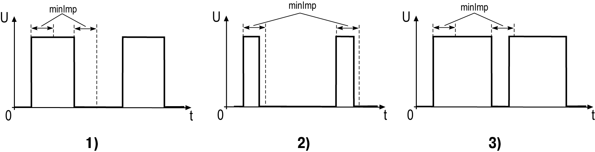
The signals arriving at the counting input of the device are filtered. The filter is characterized by the minimum allowable pulse and pause lengths (minImp parameter, ms). All pulses and pauses less than the specified duration are perceived as bounce and ignored.
The recommended value for this parameter is calculated as follows:

where MaxFreqRele is the maximum frequency (up to 100 Hz) of switching a dry contact relay.
For input frequencies greater than 100 Hz, set minImp = 10 μs.
The principle of operation of this parameter is shown in Figure:
- 1: pulse duration and pause duration greater than minImp – the signal is passed through the bounce protection system;
- 2: the pulse duration is less than minImp – the signal is not passed by the bounce protection system;
- 3: the pulse duration is greater than minImp, but the pause duration is shorter than minImp – the signal is not skipped by the chatter protection system.
Tachometer mode
When performing the function of a tachometer:
- device measures the instantaneous value of the duration of the time intervals (T) between the leading or trailing edges (in s);
- device calculates the value of N / T, where N is the value determined by the dimension of the display of the measured value;
- device displays the obtained value taking into account the scaling factor.
The tachometer measurement interval is set by the dttA parameter in:
- rps (N = 1);
- rpm (N = 60);
- rph (N = 3600)
- custom values (N = F × 10-FdP, where F and FdP are variable parameters).
If F × 10-FdP < 1, the values dependent on dttA (FrEQ, UdAC, dPro, LOR, HIR, UdO, dU) can be less than 1 (for example, 0.25) and displayed on the display as 0. This occurs because fractional display is not supported. But in the operation of the device, values with a fractional part will be used.
The dttA value affects the upper and lower limits of the FrEQ parameter. That is, the limits are recalculated in accordance with the coefficient N. For example, the values of the FrEQ parameter lie in the range [1; 2500]. With the coefficient N = 60, the boundaries of the FrEQ parameter will be as follows:
- lower limit: 1 × 60 = 60;
- upper limit: 2500 × 60 = 150000.
Counting results are shown on the display. Calculation units are displayed in the form of highlighting of single LEDs (see Table for details).
- Rounding of the measurement results is carried out in a standard mathematical way, in a big way. That is, if in a rounded digit a digit is more than or equal to 5, then one is transferred to the next digit. If the measured value lies within 0.2 ... 0.5 Hz inclusively, then a value of 1 is transmitted via Modbus to indicate the presence of a signal.
- If the digit capacity is not enough to display the selected number of digits after the decimal point, the device automatically shifts the number to the right.
An eighth-order moving average filter is used to damp the signal in the device. The MAV.L parameter defines the minimum time (in seconds) for filling the filter buffer. Adding a new value to the buffer will be done not earlier than in (MAV.L / 8) seconds. At input frequencies less than or equal to (8 /MAV.L), the settling time of the input signal to the digital signal can be longer than MAV.L. By default, this filter is enabled.
Operating time counter
The device counts the operating time if the signal level on the
operating time counter reaches a logical 1. When the device performs
this function, the LED
lights up.
To see the current operating time on display, press and hold the
button . If
you release this button, the display returns to the tachometer reading.
The measured operating time is shown on the display (see Table for details). If the current range is exceeded, the device automatically sets the next display range of the measurement results. The maximum value of the operating time takes values from 1 s to 9999 days 23 hours.
For devices with discrete output, it is possible to set the limit values of the operating time, upon reaching which the output is switched on.