Sequence of setup
The Setup mode is intended for viewing and editing the device parameters. New parameters are saved to non-volatile memory of the device.
To enter (or exit) the Setup mode, press and hold button  for
at least 2 seconds.For access to configuration setup (parameters of
connection with PC) press at the same time buttons
for
at least 2 seconds.For access to configuration setup (parameters of
connection with PC) press at the same time buttons  and and hold them for 2 sec.
While editing, if no button is pressed within 2 min., device automatically restores previous value of the parameter and returns to parameter view mode. If within 3 minutes there are no actions in Setup menu, device automatically returns to Operation.
When device enters Setup for the first time, upper indicator shows PASS. Enter a new 4-digit password (default is 0000), save it and memorise. This password is further required for changing the device settings and for restoring factory settings (dEFAUL).
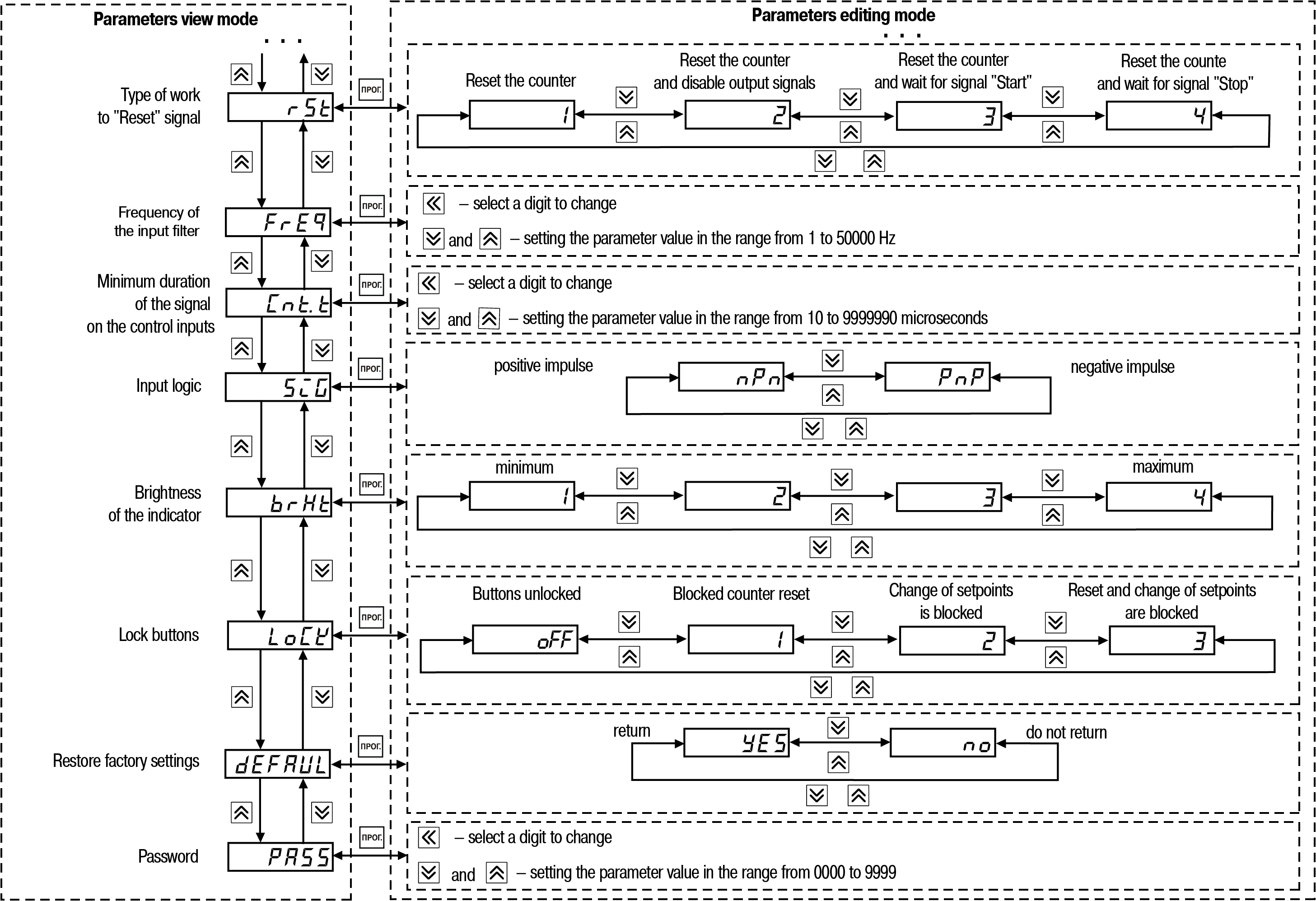
Structure of the device settings menu and sequence of pressing the buttons for setup is shown in figure and figure.

Since the FDP and DP parameters set restrictions on each other (the number of displayed digits after the decimal point in the counting results can not be larger than the number of digits after the decimal point of the entered multiplier), editing of parameters FDP, DP, F should be performed in the following sequence:
to increase the number of displayed digits after the decimal point (decimal point offset to the left):
set parameter FDP;
set parameter F;
set parameter DP;
to decrease the number of displayed digits after the decimal point (decimal point offset to the right):
set parameter DP;
set parameter FDP;
set parameter F.
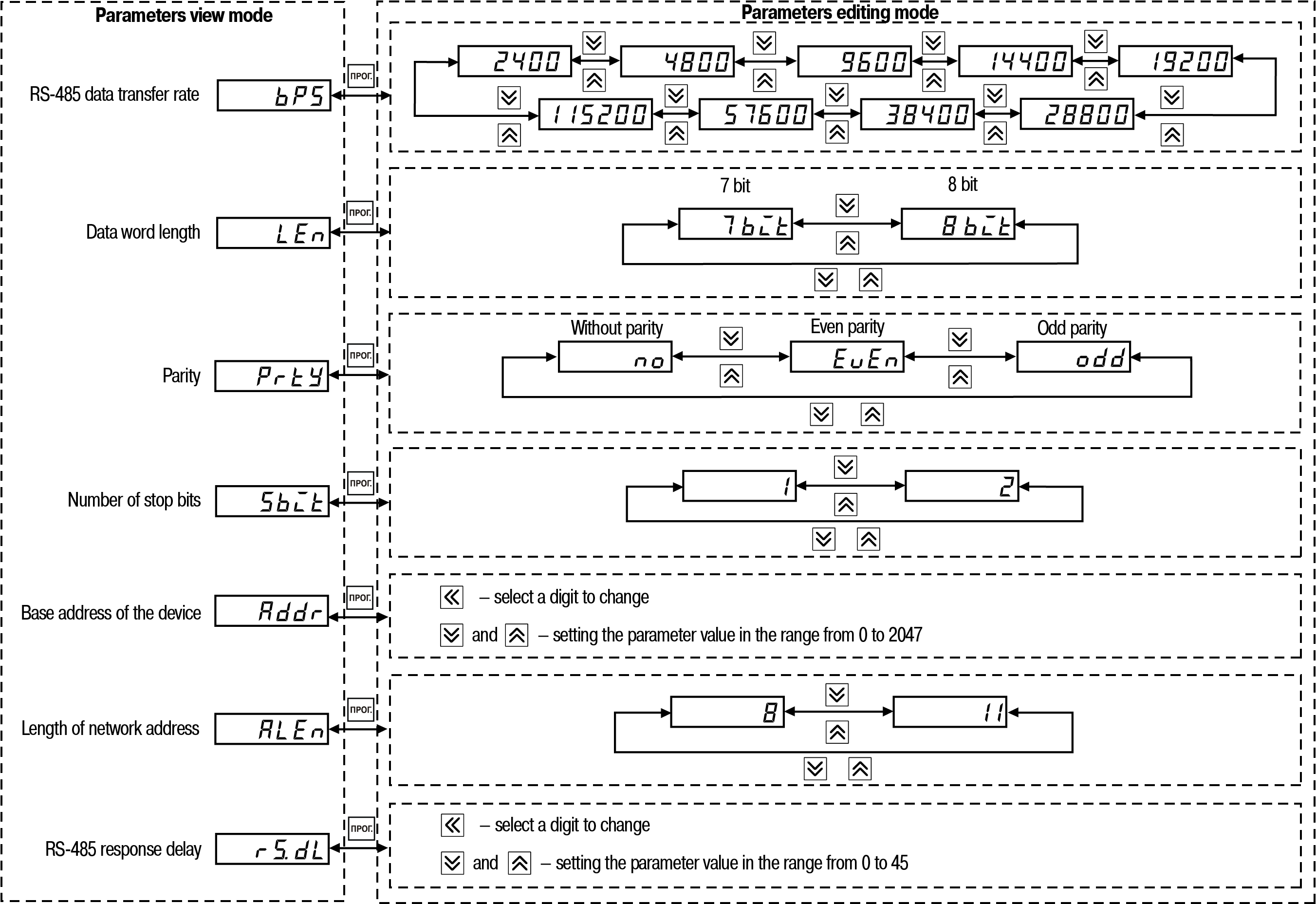
Structure of the RS-485 configuration settings menu and sequence of pressing the buttons for setup is shown in Figure.
Operating modes
Availiable types of counting (depending on the values of parameter inP) are presented in Table.
Types of counting
| Mode | Description |
|---|---|
| Count-up (inP = 1) | Input functions: Input 1 – count, Input 2 – start/stop, Input 3 – reset, Input 4 – block Operating principle: Pulse count from zero upwards. When the setpoint is reached, the corresponding output is switched and the counter is reset 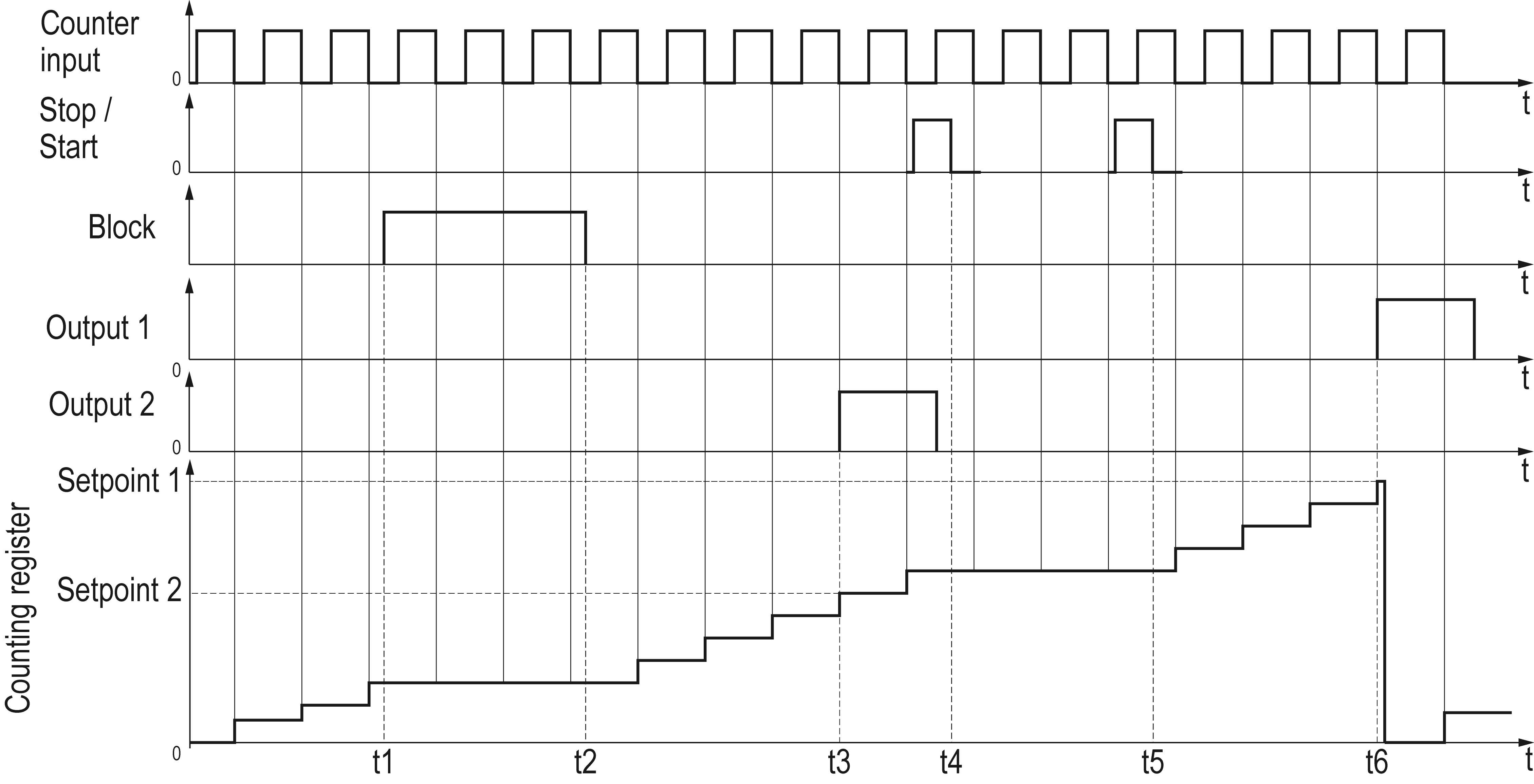 {t1–t2} – blocking signal the counting inputs; t3 – switching of output 2 in case of coincidence of values of the counting register and setpoint 2; {t4–t5} – stop-start signal; t6 – switching of output 1 in case of coincidence of values of the counting register and setpoint 1 |
| Count-down (inP = 2) | Input functions: Input 1 – count, Input 2 – start/stop, Input 3 – reset, Input 4 – block Operating principle: Counting pulseopw6z7ds from the highest by the module setpoint to zero (decreasing). When the zero is reached, corresponding output is switched and the setpoint register is written to the count register 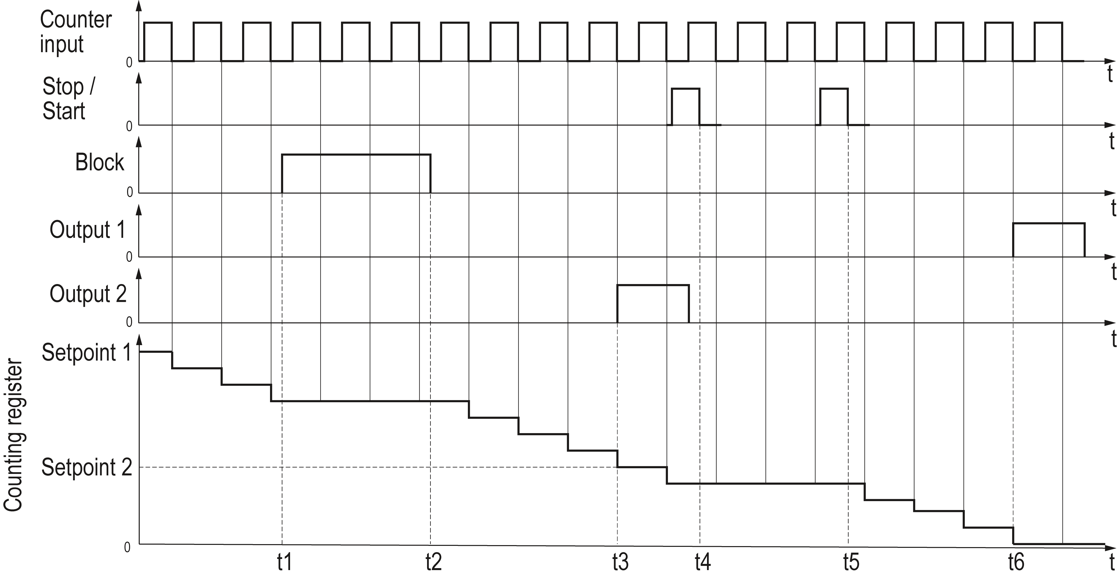 {t1–t2} – blocking signal on the counting inputs; t3 – moment of switching of output 2 in case of coincidence of values of the counting register and setpoint 2; {t4–t5} – stop-start signal; t6 – moment of switching of output 1 in case of coincidence of values of the counting register and setpoint 1 |
| Command count (inP = 3) | Input functions: Input 1 – count, Input 2 - direction of count, Input 3 – reset, Input 4 – block Operating principle: Two inputs are used: counting pulses are applied to the first, the status of the second determines the direction of the count. If there is a "logical 0" at the second output, the counter increases its value, if there is a "logical 1" it decreases. In this type two setpoints can be set, meanwhile: • if the setpoints have the same sign, counter resets after reaching the setpoint, that is larger by module. 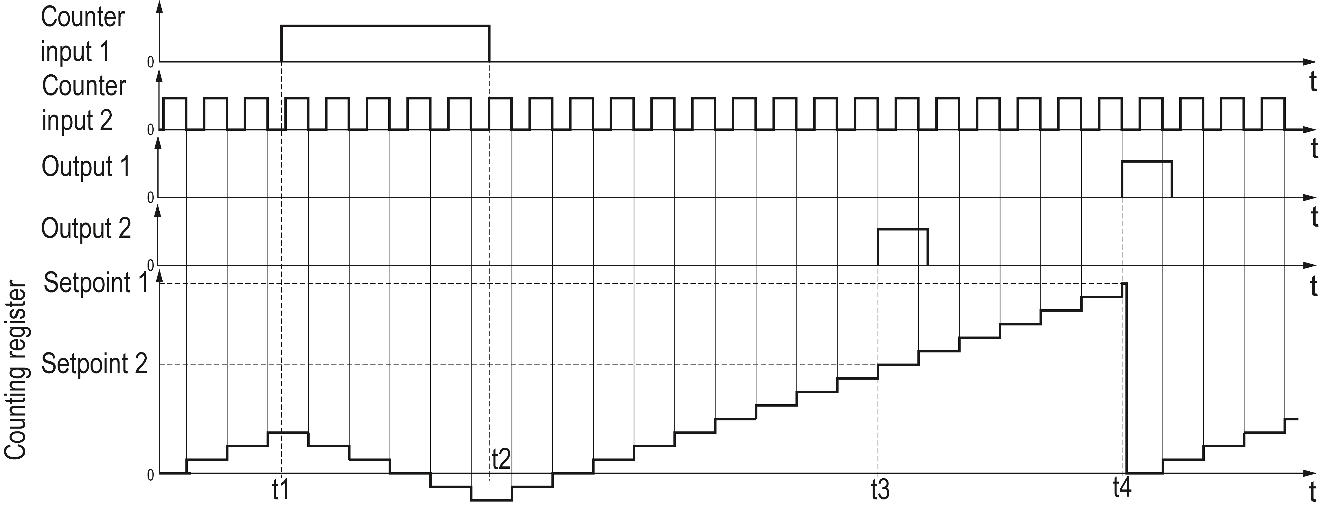 {t1–t2} – the decrease in the value of the counting register (impulse appears at the counting input 2); t3 – moment of switching of output 2 in case of coincidence of values of the counting register and setpoint 2; t4 – moment of switching of output 1 in case of coincidence of values of the counting register and setpoint 1 • if the setpoints have different signs, the counter is reset after reaching each value 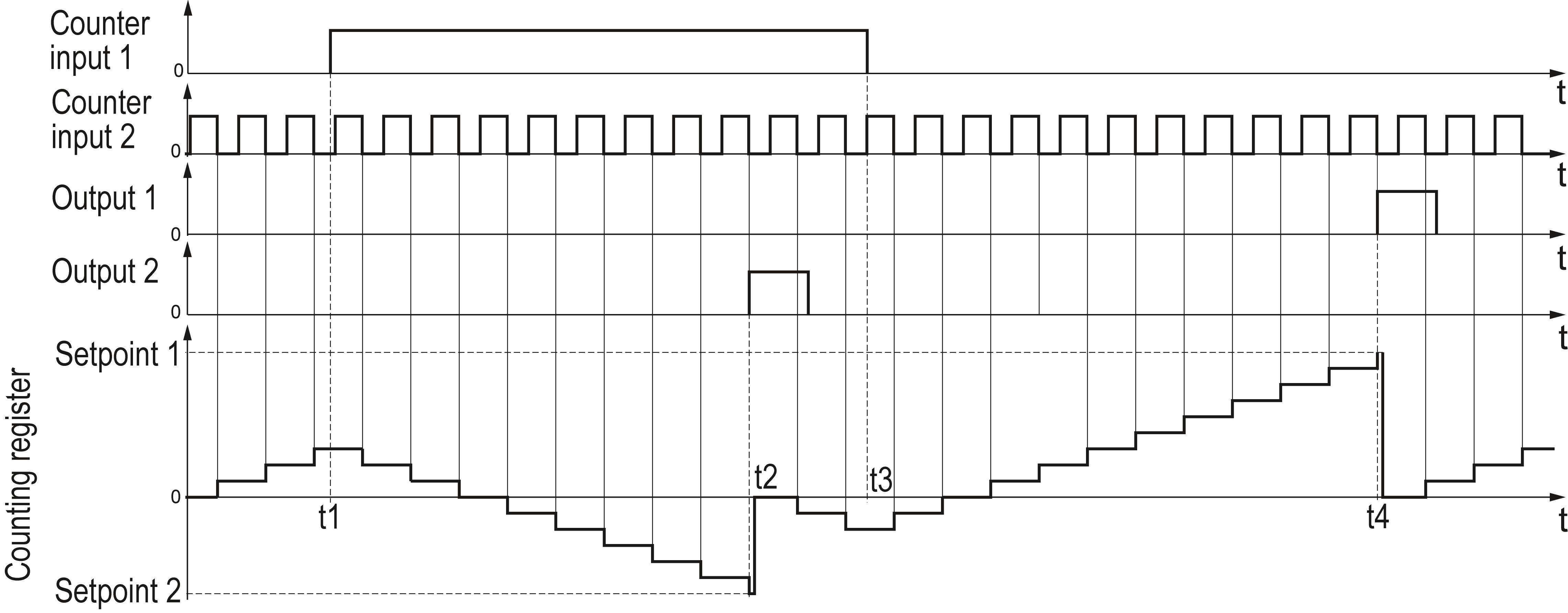 {t1–t3} – the decrease in the value of the counting register (impulse appears at the counting input 2); t2 – moment of switching of output 2 in case of coincidence of values of the counting register and setpoint 2; t4 – moment of switching of output 1 in case of coincidence of values of the counting register and setpoint 1 If
the setpoint is set as zero, it is considered to be disabled, and
the counter does not use it. |
| Individual count (inP = 4) | Input functions: Input 1 – count 1, Input 2 – count 2, Input 3 – reset, Input 4 – block Two counting inputs are used: pulses on Input 1 increase the value of the counting register, and the pulses on Input 2 decrease it. In this case, two setpoints are used (after reaching each of them, the corresponding output switches): Operating principle: • if both setpoints have the same sign, counter does not reset after reaching lesser (by module) value. Otherwise, corresponding output is switched each time counter reaches this setpoint, regardless of the direction of the count 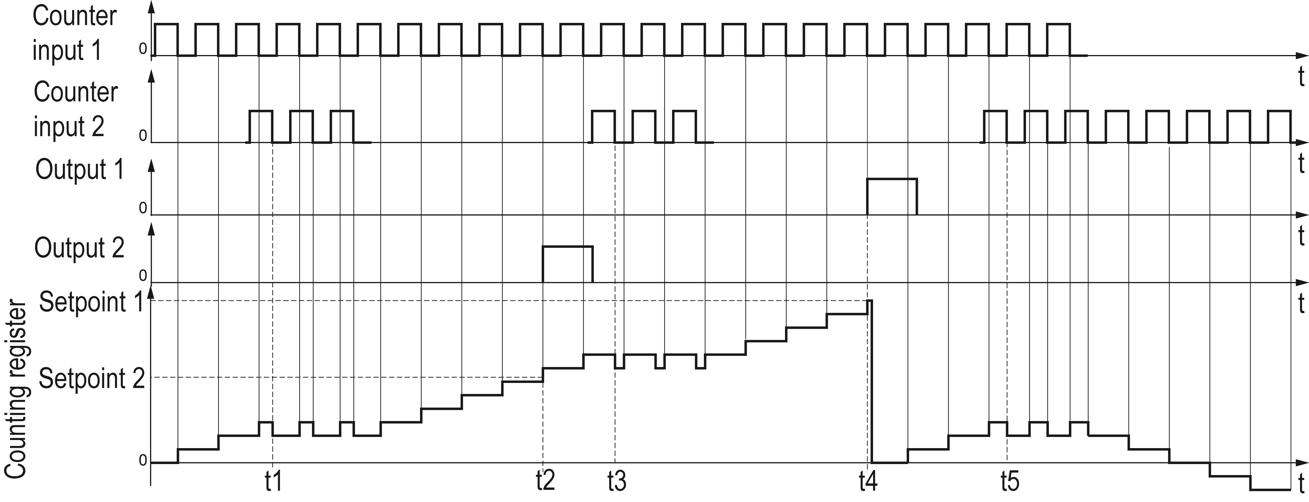 t1, t3, t5 – moments of the decrease in the value of the counting register (impulse appears at the counting input 2); t.2 – moment of switching of output 2 in case of coincidence of values of the counting register and setpoint 2; t4 – moment of switching of output 1 in case of coincidence of values of the counting register and setpoint 1 • if the setpoints have different signs (the first is greater than zero, and the second is smaller), then counter resets after reaching each setpoints 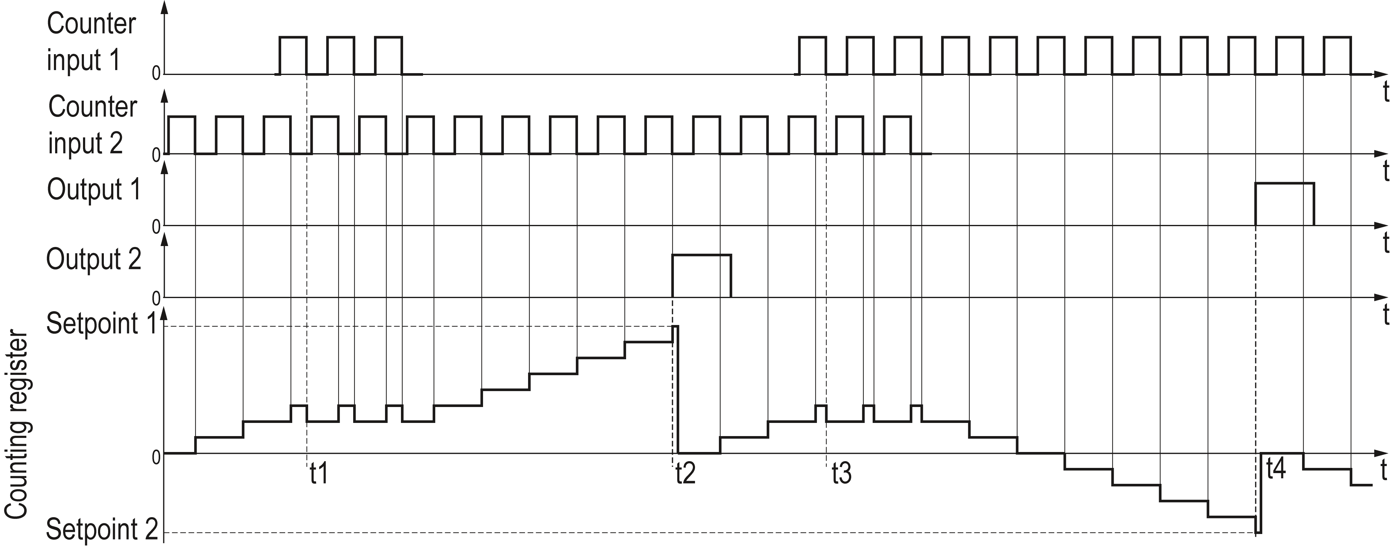 t1, t3 – moments of the decrease in the value of the counting register (the appearance of the pulse at the counting input 2); t2 – moment of switching of output 2 in case of coincidence of values of the counting register and setpoint 2; t4 – moment of switching of output 1 in case of coincidence of values of the counting register and setpoint 1 |
| Reversing count (inP = 5) | Input functions: Input 1 – count 1, Input 2 – change counting direction (reverse), Input 3 – reset, Input 4 – block Operating principle: After the power is on, the device is in the "count-up" mode by default. For reversing count it is necessary to apply signal to input 2. Thus there are two counting inputs: pulses on Input 1, lead to an increase in the value of the counter, the counting direction is changed cyclically with each incoming pulse on Input 2. In this case, two setpoints are used (after reaching each of them, the corresponding output switches): • if both the setpoints have the same sign 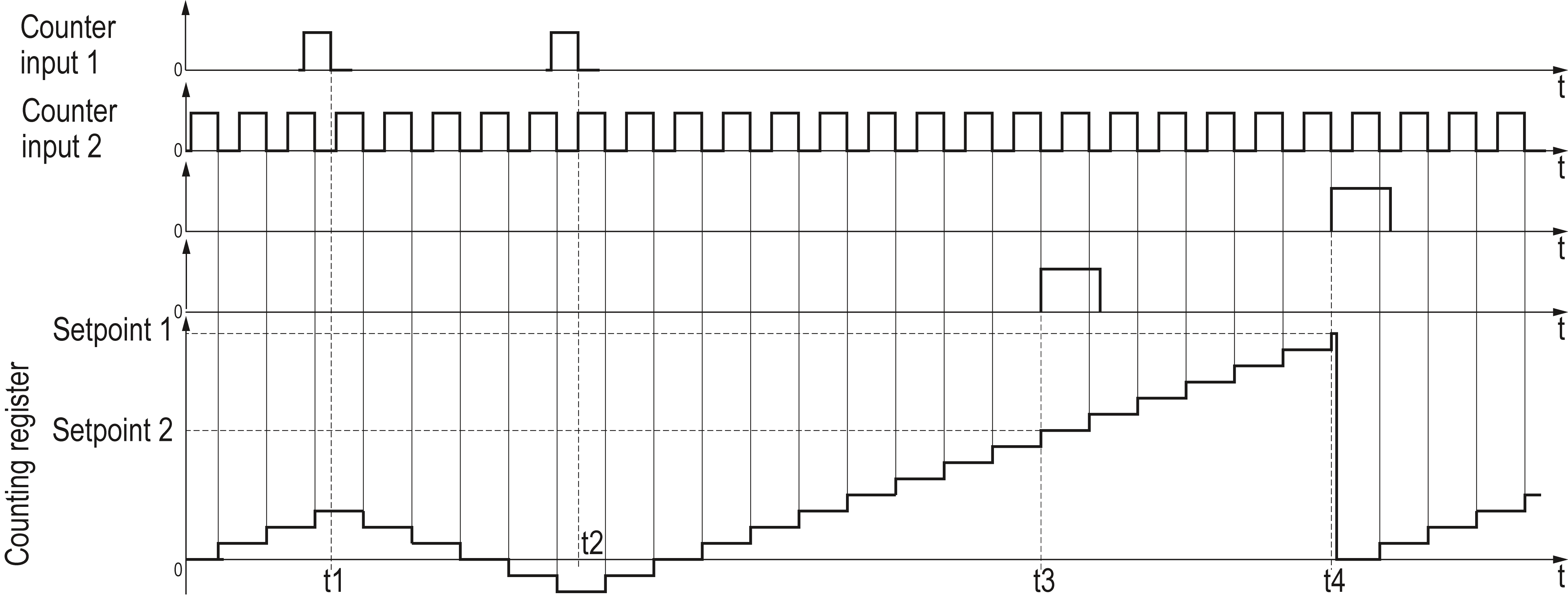 t1, t2 – moments of change of the counting direction (the appearance of the pulse at the counting input 2); t3 – moment of switching of output 2 in case of coincidence of values of the counting register and setpoint 2; t4 – moment of switching of output 1 in case of coincidence of values of the counting register and setpoint 1 • if the setpoints have different signs 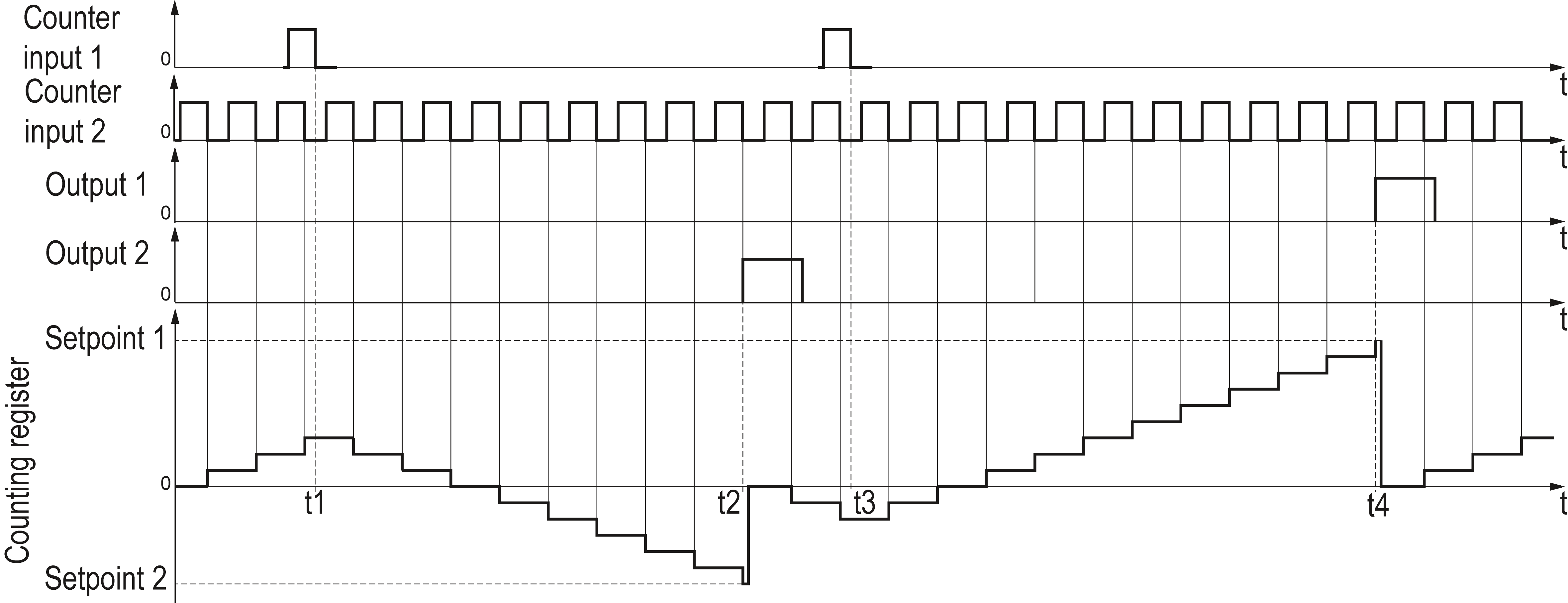
t1, t3 – moments of change of the counting direction (the appearance of the pulse at the counting input 2); t2 – moment of switching of output 2 in case of coincidence of values of the counting register and setpoint 2; t4 – moment of switching of output 1 in case of coincidence of values of the counting register and setpoint 1 |
| Quadrature / operation with encoders (inP = 6) | Input functions: Input 1 – count 1, Input 2 – count 2, Input 3 – reset, Input 4 – block Operating principle: The counting direction is determined by the meanders that come on two inputs. If the first meander is ahead of the second one, the counter counts the pulses at the first input in the increase mode, and if it lags – in the decrease mode. In this case, two setpoints are used (after reaching each of them, the corresponding output switches): • if both the setpoints have the same sign 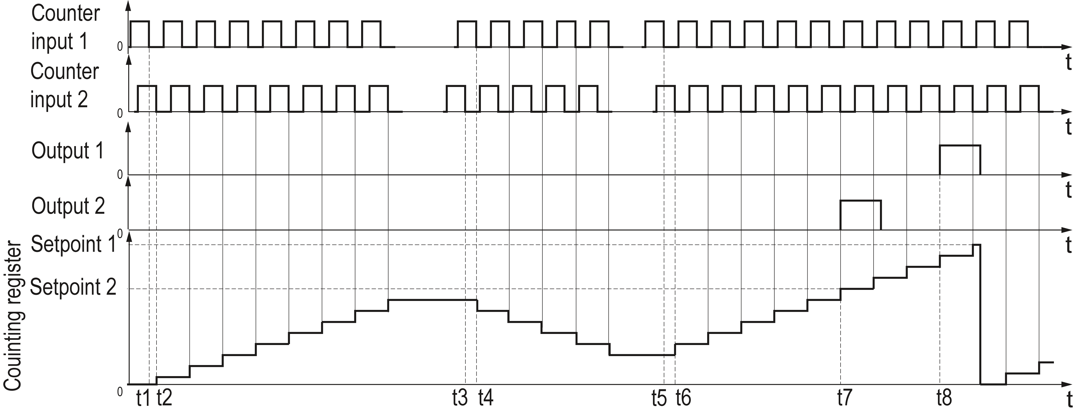 t1, t2, t5, t6 – meander at input 1 is ahead of the meander at the input 2, the counter counts in the mode of increasing the value of the count register; t3, t4 – the meander at input 1 lags behind the meander at input 2, the counter counts in the mode of decreasing the value of the counting register; t7 – moment of switching of output 2 for the time of exceeding the value of setpoint 2 by the counting register; t8 – moment of switching of output 1 for the time of exceeding the value of setpoint 1 by the counting register • if setpoints have different signs 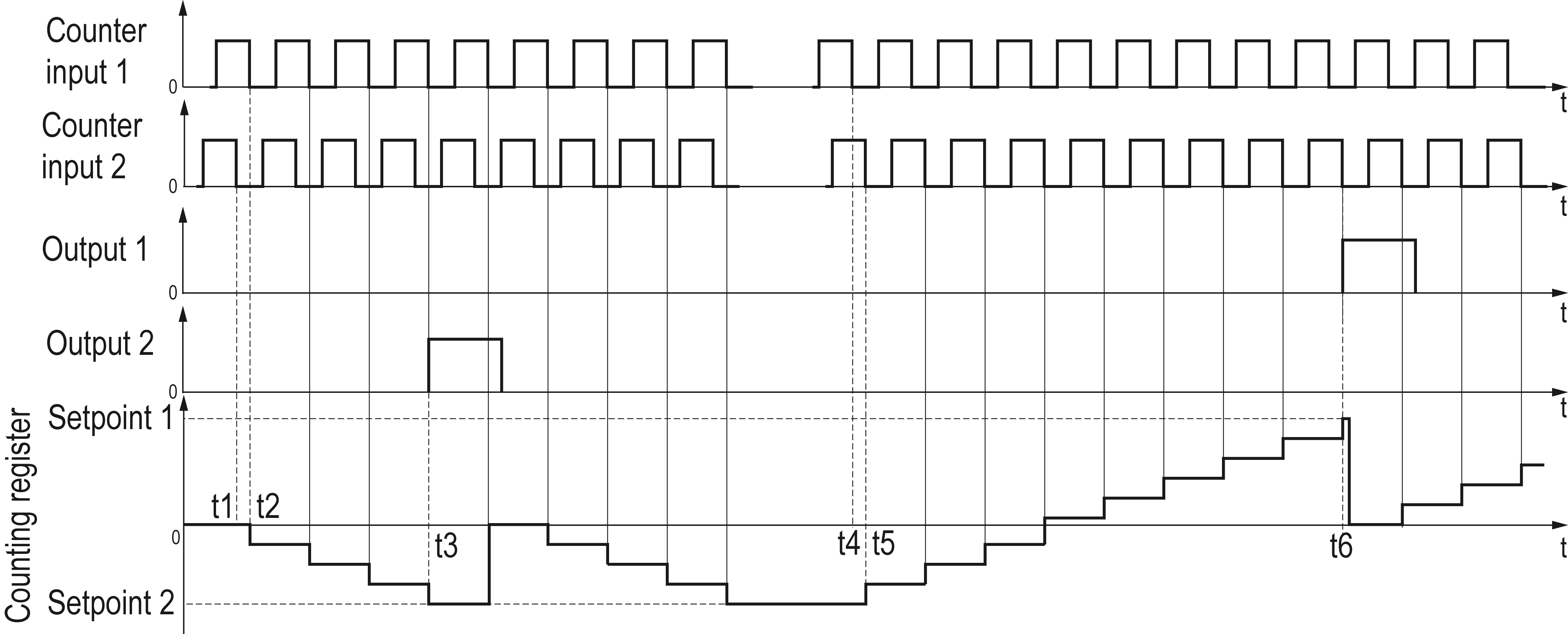 t1, t2 – the meander at input 1 lags behind the meander at input 2, the counter counts in the mode of increasing the value of the count register; t3 – moment of switching of output 2 in case of coincidence of values of the counting register and the setpoint 2; t4, t5 – the meander at input 1 is ahead of the meander at input 2, the counter counts in the mode of increasing the value of the count register; t6 – moment of switching of output 1 in case of coincidence of values of the counting register and the setpoint 1 After reaching the physical
limit of the count (if the counter does not reset after reaching the
setpoint), the device transfers the overflow result and continues
the count. |
Configuring the device from PC
Device can be configured from PC by using RS-485 and USB communication interfaces. It supports three communication protocols: OWEN, MODBUS RTU и MODBUS ASCII. Addresses, names, dimensionalities, hash-codes and other configuration parameters are given in Appendix.
Functions of the software "Configurator СИ30" (file cfgSI30.exe), which is designed for configuring the device with PC, are described in the user manual "Pulse counter, model СИ30. Configuration" on the CD supplied. The configurator can be downloaded free from the website: www.owen.ru.
Parameters for reading indications of the counter from PC are described in Table.